อินพุตของ GL840
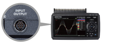
Input system 1 : Multifunction analog input ports
Contains a highly isolated input system which ensures that signals are not corrupted by noise from other channels. The GL840's inputs are suitable for combined measurements from voltage, temperature, humidity, logic, and pulse signals.
The standard configuration has 20 analog input channels. It is expandable to 200 channels by adding optional 20 channels extension terminal base unit (B-566) and input terminal units (B-564 or B-565).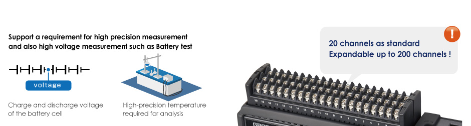
| Withstand voltage & Accuracy | Multi-input type (B-564) | Withstand-voltage type (B-565) | |
|---|---|---|---|
| Voltage | Input voltage range | 20 mV to 100 V | 20 mV to 100 V |
| Max. voltage (Input - GND) | 60 Vp-p | 300 Vp-p | |
| Temp. | Thermocouple | R, S, B, K, E, T, J, N, W (WRe5-26) | |
| RTD (Resistance Temp. Detector) | Pt100 (IEC751), Pt1000 (IEC751), JPt100 (JIS) | ||
| Accuracy | Voltage | ± 0.1% of F.S. | ± (0.05% of FS + 10μV) |
| Temperature* | ± 1.55 ºC | ± 1.1 ºC | |
* Accuracy rating for K-type thermocouple at 100˚C includes reference junction compensation. Accuracy varies by temperature levels and thermocouple types.
The following shows how a standard configuration is expanded to more than 40 channels
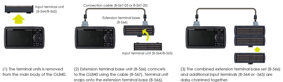
Configuration for additional channels
|
Number of channels |
20 channels |
40 channels |
100 channels |
200 channels |
|---|---|---|---|---|
|
GL840 unit (GL840-M or GL840-WV) |
1 set |
1 set |
1 set |
1 set |
|
Connection cable (B-567-05 or -20) |
N/A |
1 pc |
1 pc |
1 pc |
|
Terminal base (B-566) |
N/A |
2 sets |
5 sets |
10 sets |
|
Input terminal (B-564 or B-565 ) |
N/A |
1 set |
4 sets |
9 sets |
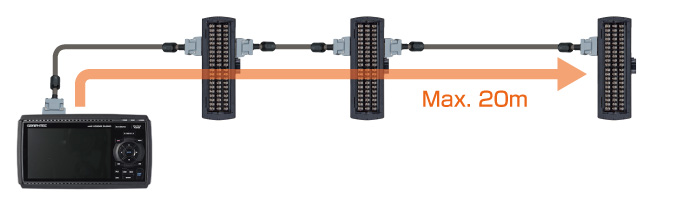
Offers longer cable for the input terminals
Input terminal blocks can be connected directly (in daisy chain), or using the B-565 cable(s). This allows the input terminals to be placed in separate locations according to the need of the application.
The input terminal unit and the GL840 main body can be extended by using an extended connections cable.
*If the signal is affected by noise, it may be required to use a slower sampling.
Input system 2 : Support digital sensors
Digital sensors and input terminal/adapters for the GL100 connects to the GL840 directly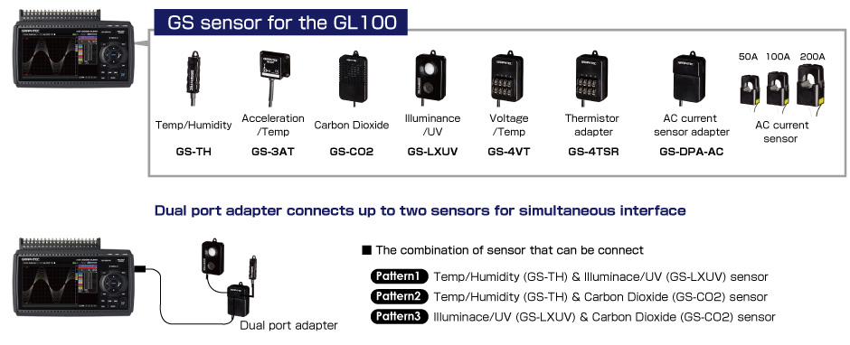
Input system 3 : 4 channels of Logic/Pulse inputs
Supports 4-channels logic or pulse signal inputs. Pulse mode allows cumulative, instant, or rotational values for industrial measurement capability with speed and flow.
GL840 Analog input specifications
| Item | Description | ||||
|---|---|---|---|---|---|
| Model number | GL840-M, Input terminal B-564 | GL840-WV, Input terminal B-565 | |||
| Input method | All channels isolated balanced input *13, Scans channels for sampling | ||||
| Type of input terminal | Screw terminal (M3 screw) | ||||
| Measurement range |
Voltage | 20, 50, 100, 200, 500 mV, 1, 2, 5, 10, 20, 50, 100 V, and 1-5V F.S. (Full Scale) | |||
| Thermocouple | Type: K, J, E, T, R, S, B, N, W (WRe5-26) Range: 100, 500, 2000 ºC *14 |
||||
| RTD (Resistance Temperature Detector) |
Type: Pt100, Pt1000 (IEC751), JPt100 (JIS) Range: 100, 500, 2000 ºC *14 |
||||
| Humidity | 0 to 100 % RH - using the humidity sensor (option B-530) | ||||
| Filter | Off, 2, 5, 10, 20, 40 (moving average in selected number) | ||||
| Measurement accuracy *15 | |||||
| Voltage | ± 0.1% of F.S. (Full Scale) | ± (0.05% of F.S. + 10μV) | |||
| Temperature (Thermocouple) *16 | |||||
| Type | Measurement range (TS: Temp Sense) |
Measurement accuracy | Measurement accuracy | ||
| R | 0 ≤ TS ≤ 100 ºC | ± 5.2 ºC | ± 4.5 ºC | ||
| 100 < TS ≤ 300 ºC | ± 3.0 ºC | ± 3.0 ºC | |||
| 300 < TS ≤ 1600 ºC | ± (0.05% of rdg. + 2.0 ºC) | ± 2.2 ºC | |||
| S | 0 ≤ TS ≤ 100 ºC | ± 5.2 ºC | ± 4.5 ºC | ||
| 100 < TS ≤ 300 ºC | ± 3.0 ºC | ± 3.0 ºC | |||
| 300 < TS ≤ 1760 ºC | ± (0.05% of rdg. + 2.0 ºC) | ± 2.2 ºC | |||
| B | 400 ≤ TS ≤ 600 ºC | ± 3.5 ºC | ± 3.5 ºC | ||
| 600 < TS ≤ 1820 ºC | ± (0.05% of rdg. + 2.0 ºC) | ± 2.5 ºC | |||
| K | -200 ≤ TS ≤ -100 ºC | ± (0.05% of rdg. + 2.0 ºC) | ± 1.5 ºC | ||
| -100 < TS ≤ 1370 ºC | ± (0.05% of rdg. + 1.0 ºC) | ± 0.8 ºC | |||
| E | -200 ≤ TS ≤ -100 ºC | ± (0.05% of rdg. + 2.0 ºC) | ± 1.0 ºC | ||
| -100 < TS ≤ 800 ºC | ± (0.05% of rdg. + 1.0 ºC) | ± 0.8 ºC | |||
| T | -200 ≤ TS ≤ -100 ºC | ± (0.1% of rdg. + 1.5 ºC) | ± 1.5 ºC | ||
| -100 < TS ≤ 400 ºC | ± (0.1% of rdg. + 0.5 ºC) | ± 0.6 ºC | |||
| J | -200 ≤ TS ≤ -100 ºC | ± 2.7 ºC | ± 1.0 ºC | ||
| -100 < TS ≤ 100 ºC | ± 1.7 ºC | ± 0.8 ºC | |||
| 100 < TS ≤ 1100 ºC | ± (0.05% of rdg. + 1.0 ºC) | ± 0.6 ºC | |||
| N | -200 ≤ TS < 0 ºC | ± (0.1% of rdg. + 2.0 ºC) | ± 2.2 ºC | ||
| 0 ≤ TS ≤ 1300 ºC | ± (0.1% of rdg. + 1.0 ºC) | ± 1.0 ºC | |||
| W | 0 ≤ TS ≤ 2000 ºC | ± (0.1% of rdg. + 1.5 ºC) | ± 1.8 ºC | ||
| R.J.C. | ± 0.5 ºC | ± 0.3 ºC | |||
| Temperature (RTD) *17 | |||||
| Type | Measurement range (TS: Temp Sense) |
Accuracy | Accuracy | ||
| Pt100 | -200 ≤ TS ≤ 100 ºC | ± 1.0 ºC | ± 0.6 ºC | ||
| 100 < TS ≤ 500 ºC | ± 0.8 ºC | ||||
| 500 < TS ≤ 850 ºC | ± 1.0 ºC | ||||
| Pt1000 | -200 ≤ TS ≤ 100 ºC | ± 0.8 ºC | ± 0.6 ºC | ||
| 100 < TS ≤ 500 ºC | ± 0.8 ºC | ||||
| JPt100 | -200 ≤ TS ≤ 100 ºC | ± 0.8 ºC | ± 0.6 ºC | ||
| 100 < TS ≤ 500 ºC | ± 0.8 ºC | ||||
| A/D converter | Sigma-Delta type, 16 bits (effective resolution: 1/40000 of the measuring full range) | ||||
| Input resistance | 1MΩ ±5% | ||||
| Allowable signal source resistance | Up to 300Ω | Up to 100Ω | |||
| Maximum input voltage |
Between (+) / (-) terminal |
20 mV to 2 V range: 60 Vp-p, 5 V to 100 V range: 110 Vp-p |
|||
| Channels ((-) / (-)) | 60 Vp-p | 600 Vp-p | |||
| Channel / GND | 60 Vp-p | 300 Vp-p | |||
| Max. voltage (withstand) |
Between channels | 350 Vp-p (1 minute) | 600 Vp-p | ||
| Channel / GND | 350 Vp-p (1 minute) | 2300 Vrms AC (1 minute) | |||
- *13
- The terminal "b" for using the RTD is connected each other across all channels.
- *14
- If the specifications of the temperature sensor is lesser or greater than the selected measurement range, GL840
can measure up to the specifications of the sensor. - *15
- Subject to the following conditions:
- Room temperature is 23 oC ± 5 oC.
- When 30 minutes or more have elapsed after power has turned on.
- Filter is set to 10.
- Sampling rate is set to 1 sec, using 20-channel in GL840-M and 10-channel in GL840-WV.
- GND terminal is connected to ground.
- *16
- Wire size of thermocouple used is 0.32mm diameter in the T or K type and 0.65mm diameter in other types.
- *17
- Supports 3-wire type sensor.

