High speed 1 MS/s simultaneous sampling with isolated input
GL2000 is equipped with an isolated input mechanism to protect signals from interferences caused by noise from other channels. 16-bit A/D converter adopted to achieve hi-speed and hi-resolution measurement.
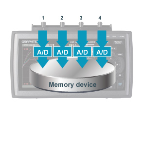 Simultaneous sampling
GL2000 utilizes simultaneous sampling to eliminate slowdown in sampling rate by using multiple A/D converters in simultaneous sampling method. Four individual A/D converters in each channel sustains the maximum sampling speed for all four channels to measure high speed rapid voltage fluctuation and multi-channel vibration measurement.
Sampling interval: 1 µs to 1 min (in steps of 1, 2, 5)
External sampling function
Sampling of the logger is performed in sync with an external device using an external signal input.
Maximum input frequency: 100 kHz * B-513 Input/Output cable for GL is required.
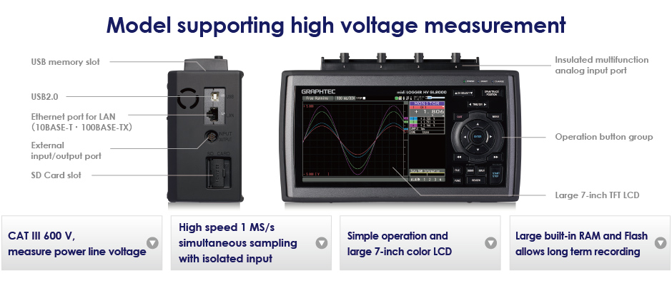
Multifunction input with CAT III measurement category
Voltage, temperature, humidity, logic and pulse measurements can all be taken simultaneously in high speed.
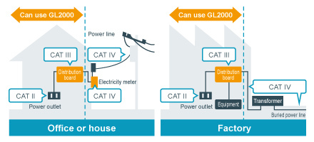
CAT III 600 V is compatible with measuring power supply circuit in an equipment that captures power directly from the distribution panel.
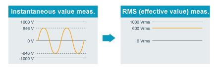
Measures abnormalities in a repeated waveform by effectively measuring the corresponding RMS value
- In 1000 Vrms range, Crest Factor is up to 1.41
* Maximum rated safety voltage: 600 V rms, Peak voltage: 850V - In other range, Crest Factor is up to 2.0
Analog input specifications
| Item | Description | |||
|---|---|---|---|---|
| Number of input channels | 4 channels | |||
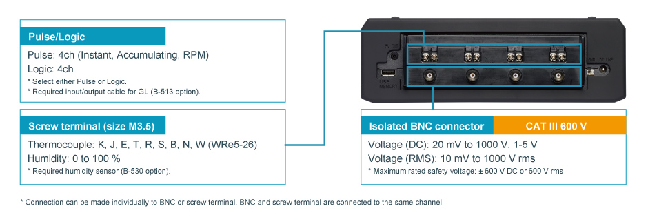
| Type of input terminal | Isolated BNC connector and Screw terminal (M3.5 screw) (*7) | |||
| Input method | All channels isolated unbalanced input, Simultaneous sampling | |||
| Sampling speed (interval) | 1 M Samples/s to 1 Sample/min (1 μs to 1 min) and External (*8) • Sampling interval: 1, 2, 5, 10, 20, 50, 100, 200, 500 μs, 1, 2, 5, 10, 20, 50, 100, 200, 500 ms, 1, 2, 5, 10, 20, 30 sec, 1 min * When using built-in RAM: 1 μs to 1 min, using other storage: 1 ms to 1 min |
|||
| Frequency response | DC to 200 kHz (within +1/-4 dB) | |||
| Measurement range |
Voltage (DC) | 20, 50, 100, 200, 500 mV, 1, 2, 5, 10, 20, 50, 100, 200, 500, 1000 V, and 1-5V F.S. * Max. rated safety voltage: ± 600 V DC |
||
| DC-RMS (DC coupling and rms value meas.) |
10, 25, 50, 100, 250, 500 mV rms, 1, 2.5, 5, 10, 25, 50, 100, 250, 500, 1000 V rms F.S. * Max. rated safety voltage: 600 V rms • Crest Factor: in 1000 V range, up to 1.4 (peak: max. 850 V), in other range, up to 2 • Frequency response: 20 Hz to 10 kHz • Measures the accumulated value of the DC and AC components in effective value, that is a true-RMS. |
|||
| Temperature | Thermocouple: K, J, E, T, R, S, B, N, W (WRe5-26) | |||
| Humidity | 0 to 100 % RH - using the humidity sensor (option B-530) | |||
| Filter (Low pass) | Off, Line (1.5 Hz), 5, 50, 500 Hz, 5, 50 kHz (at -3dB, -6dB/oct) | |||
| A/D converter | 16-bit (effective resolution: 1/40000 of the measuring full range) | |||
| Measurement accuracy (*9) |
Voltage (DC) | ± 0.25% of Full Scale | ||
| Voltage (RMS) | ± 1.5% of Full Scale (Sine wave in 20 Hz - 10 kHz) | |||
| Temperature (Thermocouple) (*10) |
Type | Measurement range | Measurement accuracy | |
| R/S | 0 ≤ TS ≤ 100 ºC 100 < TS ≤ 300 ºC R: 300 < TS ≤ 1600 ºC S: 300 < TS ≤ 1760 ºC |
± 7.0 ºC ± 5.0 ºC ± (0.05 % of reading + 3.0 ºC) ± (0.05 % of reading + 3.0 ºC) |
||
| B | 400 ≤ TS ≤ 600 ºC 600 < TS ≤ 1820 ºC |
± 5.5 ºC ± (0.05 % of reading + 3.0 ºC) |
||
| K | -200 ≤ TS ≤ -100 ºC -100 < TS ≤ 1370 ºC |
± (0.05 % of reading + 3.0 ºC) ± (0.05 % of reading + 2.0 ºC) |
||
| E | -200 ≤ TS ≤ -100 ºC -100 < TS ≤ 800 ºC |
± (0.05 % of reading + 3.0 ºC) ± (0.05 % of reading + 2.0 ºC) |
||
| T | -200 ≤ TS ≤ -100 ºC -100 < TS ≤ 400 ºC |
± (0.1 % of reading + 2.5 ºC) ± (0.1 % of reading + 1.5 ºC) |
||
| J | -200 ≤ TS ≤ -100 ºC -100 < TS ≤ 100 ºC 100 < TS ≤ 1100 ºC |
± 3.7 ºC ± 2.7 ºC ± (0.05 % of reading + 2.0 ºC) |
||
| N | -200 ≤ TS < 0 ºC 0 ≤ TS < 1300 ºC |
± (0.1 % of reading + 3.0 ºC) ± (0.1 % of reading + 2.0 ºC) |
||
| W | 0 ≤ TS ≤ 2315 ºC | ± (0.1 % of reading + 2.5 ºC) | ||
| Reference Junction Compensation (R.J.C.) accuracy: ± 1.0 ºC | ||||
| R.J. Compensation | Internal or External | |||
| Burnout | Detecting burnout of Thermocouple with menu operation in free-run mode | |||
| Input impedance | 1 MΩ ±5% | |||
| Signal source impedance | up to 1 kΩ | |||
| Maximum input voltage |
Between (+) - (-) terminal |
20 mV to 2 V range: 30 V DC/AC, 5 V to 1000 V range: 600 V DC/AC |
||
| Between channels (-) - (-) terminals) |
600 V DC/AC (CAT III) (*) Transient overvoltage (impulse voltage) 6000V |
|||
| Between channel - GND |
600 V DC/AC (CAT III) (*) Transient overvoltage (impulse voltage) 6000V |
|||
| Maximum voltage (withstand) |
Between channels |
5400V DC/AC (1 minute) | ||
| Between channels - GND |
5400V DC/AC (1 minute) | |||
| Isolation resistance | Min. 50 MΩ (at 500 V DC) with between input and GND | |||
| Common-mode rejection ratio | Min. 90 dB (50/60 Hz, signal source impedance: max. 300 Ω) | |||
| Signal-noise ratio (S/N) | 20 mV range: - 40 dB (when input terminals + and - are shorted) Other range: - 50 dB (when input terminals + and - are shorted) |
|||
- (*7)
- Connections can be made individually to BNC terminal or M3.5 screw terminal.
- (*8)
- Required Input/Output cable for GL series (B-513) option for connecting signal.
- (*9)
- Subject to the following conditions:
• Room temperature is 23 ºC ± 5 ºC.
• When 30 minutes or more have elapsed after power has turned on.
• Filter is set to Line (1.5 Hz) in DC measurement and temperature.
• GND terminal is connected to ground.
• It is placed vertically.
• Average of the measured values is used. - (*10)
- Wire size of Thermocouple used is 0.32mm diameter in the T and K type, and 0.65mm diameter in other types.
External input & output signal specifications
| Item | Description | |
|---|---|---|
| External input/output |
Input (*11, *12) | Logic or Pulse (4 channels), Trigger or Sampling (1 channel) |
| Output (*11, *13) | Alarm (4 channels) or Trigger (1 channel) with Alarm (3 channels) | |
| Input signal specification |
Logic and Pulse | Voltage range: 0 to +30 V (common ground) Threshold: Approx. +2.5 V Hysteresis: Approx. 0.5 V (+2.5 to +3 V) |
| External trigger and sampling |
Voltage range: 0 to +30 V (common ground) Threshold: Approx. +1.9 V Hysteresis: Approx. 0.2 V (+1.9 to +2.1 V) |
|
| Logic measurement | Measures the status (H or L) of the signal input to each channel | |
| Pulse measurement |
Measurement | Counts pulse signals input to each channel |
| Pulse count detection cycle |
10 μs to 1 hr. (Set separately from analog signal sampling interval) | |
| Maximum pulse input |
Maximum input frequency: 100 kHz, Maximum count number: 15 M count (24 bit counter) |
|
| Measurement mode |
Rotation: Counts the number of pulses per detection cycle and then converts measured value to rotation in rpm • Span: 0 to 500 M rpm/F.S. |
|
| Accumulating: Accumulates the number of pulses count per detection cycle from the start of measurement • Span: 0 to 20 M count/F.S. (Span is set automatically) |
||
| Instant: Counts the number of pulses per detection cycle • Span: 0 to 20 M count/F.S. |
||
| External trigger input (*11) | Executes specified trigger action | |
| External sampling input (*11) | Executes sampling of measurement signal with each external sampling signal • Maximum input frequency: 100 kHz (Time error: 1 μs or less) |
|
| Output signal | Alarm output | Open collector (pull-up to 5 V with 10 kΩ resistor) • Maximum load is the 24 V and 100 mA |
| Trigger output | When a trigger is detected, output terminal releases approximately 500 μs width pulse (Low active) | |
- (*11)
- Required Input/Output cable for GL series (B-513) option for connecting signal.
- (*12)
- Select either Logic input (4 channels) or Pulse input (4 channels), select either external Trigger input or Sampling input.
- (*13)
- Select either Trigger output (1 channel) or Alarm output (1 channel). Available 3 channels Alarm output always.

