DC Strain Module GL7-DCB
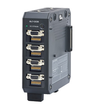 This is the input module for the sensors based on the strain gauge capable of measuring a variety phenomena as acceleration, pressure, force. It is able to connect the sensor directly and also able to measure the voltage, and resistance. Elements of the bridge circuit for the strain gauge are built in the module, and it also has the excitation power for the strain gauges and sensors. It allows to make easily measurement.
Filter function
 It is able to have high-precision measurement using various filters as low-pass, and anti-aliasing filter.
Application examples
| Industry | Agriculture, Forestry, and Fisheries |
Construction & Public Works |
Machinery industry | Electrical equipment industry |
Transportation equipment industry |
Energy (Electricity, Gas) |
|---|---|---|---|---|---|---|
| Application examples |
Pressure of fishing nets | Strain of the building | Distortion of the press | Substrate strain | Distortion in the opening and closing of the door | Distortion of the structure |
| Water pressure measuremen | Research and maintenance of structure | Distortion of welding | Distortion at the opening and closing operation | Distortion in the vibration | ||
| Load of the structure | Tensile strength test | Distortion of body |
GL7-DCB specification
| Item | Description | |
|---|---|---|
| Type of module | DC bridge amplifier module - for strain gauge or sensor based on a strain gauge - | |
| Model number | GL7-DCB | |
| Number of input channels | 4 channels | |
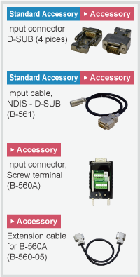
| Input method | All channels isolated balanced input, Simultaneous sampling, D-SUB type connector (9 pins, receptacle) |
|
| Sampling speed (interval) | 100 k Samples/s to 1 Sample/h (10 μs to 1 hr.) | |
| Built in RAM | 2 million samples for each channel | |
| Input type | Strain, Voltage, Resistance value (including potentiometer) | |
| Measurement range | Strain | 500, 1000, 2000, 5000, 10000, 20000 με (με: 10-6 strain) 0.2, 0.25, 0.4, 0.5, 1, 2, 2.5, 4, 5, 10 mV/V * Available ranges vary by the excitation voltage for the bridge. |
| Voltage | 1, 2, 5, 10, 20, 50, 100, 200, 500 mV, 1, 2, 5 V Full Scale | |
| Resistance | 1, 2, 5, 10, 20, 50, 100, 200, 500 Ω, 1, 2, 5, 10, 20, 50 kΩ Full Scale | |
| Measurement accuracy (*1) | Strain | ±(0.2% of Full Scale + 10 με) |
| Voltage | ±(0.2% of Full Scale + 10 μV) | |
| Resistance | ±0.5% of Full Scale (More than 1 hour elapsed after power-on) | |
| A/D converter | Successive Approximation type, 16 bits (effective resolution: 1/40000 of the measuring full range) | |
| Input impedance | 10 MΩ ±5% | |
| Gauge ratio | 2.0 constant | |
| Supported sensor | Strain (*2) | Strain gauge Quarter bridge (single gauge) in 2-, 3- or 4-wire (supports remote sensing in 3- or 4-wire) Half bridge (dual gauge) in 3-, 4-, 5-wire (supports remote sensing in 4- or 5-wire) Full bridge (quad gauge) in 4- or 6-wire (supports remote sensing in 6-wire) |
| Transducer/sensor based on a strain gauge Full bridge type in 4-wire, Full bridge type in 6-wire (supports remote sensing) |
||
| Resistance | Resistor, Potentiometer | |
| Bridge resistance | 50 Ω to 10 kΩ * Available excitation power varies by selection of element. | |
| Built-in element of the bridge | 120 or 350 Ω for the quarter- and half-bridge * Available excitation power varies by selection of element. |
|
| Excitation power | Voltage mode | 1, 2, 2.5, 5, 10 V DC * Excitation voltage 5 and 10 V is available when bridge resistance is the 350 Ω or higher. |
| Current mode | Constant current: 0.1 to 20 mA (supported voltage is up to 10 V.) | |
| Zero Adjust for Strain gauge | Method | Fully automatic (via push button or setting the condition menu) |
| Max. Range | ±10,000με (με:10-6 Strain) | |
| Remote sensing | 3- or 4-wire in quarter bridge, 4- or 5-wire in half bridge, 6-wire full bridge | |
| Shunt Calibration | Approx. 60 kΩ (120 Ω gauge), Approx. 175 kΩ (350 Ω gauge) | |
| Maximum input voltage | Between (+) / (-) terminal | 10 V, Common-mode voltage: 10 Vrms AC |
| Between channels ((-) terminals) | 10 Vp-p | |
| Between channel / GND | 60 Vp-p | |
| Max. voltage (withstand) | Between channels | 1000 Vp-p (1 minute) |
| Between channel / GND | 1000 Vp-p (1 minute) | |
| Isolation | Between channel / GND | Min. 100 MΩ (at 500 V DC) |
| Common-mode rejection ratio | Min. 80 dB (50/60 Hz, Signal source impedance: Max. 300 Ω) | |
| Frequency response | DC to 20 kHz | |
| Filter | Low pass | Off, Line (1.5 Hz), 3, 6, 10, 30, 50, 60, 100, 300, 500 Hz, 1k, 3k, 5k, 10k Hz (in -30dB/oct) |
| Anti-aliasing | Off, On | |
| Support TEDS | Standard | IEEE 1451.4 Class2 (Temperate No.33) |
| Support | Reading information from the sensor and setting it to module | |
| External dimensions (W x D x H) | Approx. 49 x 136 x 160mm (Excluding Protection) | |
| Weight | Approx. 840 g | |
- (*1)
- Subject to the conditions:
● Room temperature is 23℃ ±5℃. ● When 30 minutes or more have elapsed after power was turned on.
● Filter is set to 10 or Line. ● GND terminal is connected to ground. - (*2)
- ● Remote sensing is not available when a NDIS connector is used. ● When a bridge box is used, the connection needs to be 4-wire or 6-wire full bridge. When connecting with a Half bridge (Opposite side), an additional bridge box is required. ● Bridge excitation: Constant current drives a strain gauge type sensor or a 4-wire full bridge. ● The shunt calibration is available only when the connection is using a 3-wire, 4-wire quarter bridge, 5-wire full bridge, or 6-wire full bridge.

